Home automation with Raspberry Pi and Rust
Recently I came up with an interesting idea that finally puts to work my old dusty Raspberry Pi: home automation. More specifically, I'd like to control lights and measure current temperature and humidity in my house. Of course, lots of people did it before many times, and there are plenty of resources, tools and libraries that make it extremely easy to achieve this goal; however, they take away from you all the fun of figuring out how things actually work. Another issue is that most of existing tools are written in C, which is unsafe and cryptic. Taking these reasons into account, I decided to write all the code that controls devices from scratch in Rust, and that's what this article is about.
Preparation and building
Before writing any code, I had to plan what exactly I wanted to control and how. In case of temperature and humidity sensors, there were many choices, but since I didn't have any specific requirements, I just chose the cheapest and simplest model that was there: DHT-22. It cost around 7 EUR on Amazon and had a simple serial interface.
In case of lights, things were more complex. Since I rented a flat, I couldn't change how electricity flows into bulbs, therefore I had to decline an idea of controlling ceiling lights. Instead I decided to control only a floor lamp near the couch and Christmas lights that were still hanging above the table. At first I wanted to alter the lamp and lights themselves, but since they were using plain AC power sockets, I decided to go with a "smart socket" solution where the lamp and lights plug into sockets and RPi controls the sockets.
Now, what exactly does it mean "to control power sockets with Raspberry Pi"? RPi can control things through its General Purpose I/O interface aka GPIO; that is, basically, a set of pins on the board which can either input or output 0 or 3.3VDC. The problem is that it can't be the source of electricity for power sockets because they need 220VAC. Luckily, there are special electric switches, called "relays", which allow you to control the flow of AC using DC signal. The simplest relay is just a coil which generates magnetic field that controls a switch. I went for this one, though it is possible to spend a bit more money and buy a solid-state relay which does not produce clicking sound when it turns off and on.
Another things which are really handy when working with RPi's GPIO are breadboard, T-cobbler and multimeter. Breadboard makes it very easy to build circuits; T-cobbler maps GPIO ports into breadboard's sockets and labels them; multimeter is used to debug GPIO because it measures voltage, current and resistance.
My final shopping list was:
- DHT-22 temperature and humidity sensor (7 EUR)
- 4-channel 5V relay module (10 EUR)
- Breadboard (7 EUR)
- GPIO T-Cobbler for Raspberry Pi (12 EUR)
- Set of jumper wires (7 EUR)
- Set of resistors (9 EUR)
- Couple of power sockets (6 EUR)
- Light switch (2 EUR)
- Copper wires for AC installation, screws, plastic connectors, etc. (10 EUR)
70 EUR in total. Pretty much the cost of two usual "smart" power sockets.
Below is a connection schema for the system:

Thick lines stand for AC current cables, thin ones are for DC current, just like in real life. As you can see, DHT-22 sensor needs a pull-up resistor to keep line high when no communication is in place. AC relay doesn't need it since it's mechanical inside and slight noise in a line won't hurt or falsely trigger it.
Controlling GPIO
Now, when everything is ready, it's time to figure out how actually RPi can
control things. As I mentioned before, it has a set of special IO pins, called
GPIO. Usually they are accessible through a set of registers in internal memory
of MCU: you write to a specific register to enable selected pin, choose its
operational mode, enable interrupts, etc. Raspbian Linux exposes internal MCU
memory via virtual device /dev/mem; it's more convenient, however, to use
/dev/gpiomem for GPIO control because it doesn't require root privileges.
Memory layout for GPIO can be found in the datasheet of your processor; in case
of my Raspberry Pi 2 Model B, it's
BCM2835.
Implementation of GPIO driver is straightforward: first, it opens /dev/gpiomem
and maps it into RAM using mmap; then gets access to it whenever it is
required to change operation mode of a pin or communicate through it:
extern crate libc;

use self::libc::{c_void, c_int, c_char, open, close, mmap, munmap,
    O_RDWR, O_SYNC, PROT_READ, PROT_WRITE, MAP_SHARED, MAP_FAILED};
use std::ffi::CString;
use std::io;
use std::ptr;
use std::result;


pub struct GPIO {
    mem: *mut u32,
}

#[derive(Eq, PartialEq, Copy, Clone)]
pub enum Mode {
    Input,
    Output,
}

#[derive(Debug)]
pub enum Error {
    IOError(io::Error),
    CantOpenGPIOMem,
    CantMapGPIOMem,
}

type Result<T> = result::Result<T, Error>;

impl GPIO {
    pub fn new() -> Result<GPIO> {
        let gpio_fd = open_gpio_mem()?;
        let mem = map_gpio_mem(gpio_fd)?;
        Ok(GPIO { mem: mem as *mut u32})
    }

    pub fn set_mode(&mut self, pin: u8, mode: Mode) {
        check_pin_num(pin);
        let offset = pin as isize / 10;
        let shift = 3 * (pin as isize % 10);
        unsafe {
            *self.mem.offset(offset) &= !(7 << shift);
            if mode == Mode::Output {
                *self.mem.offset(offset) |= 1 << shift;
            }
        }
    }

    pub fn set_high(&mut self, pin: u8) {
        check_pin_num(pin);
        unsafe { *self.mem.offset(GPIO_MEM_OUTPUT_SET_OFFSET / 4) = 1 << pin; }
    }

    pub fn set_low(&mut self, pin: u8) {
        check_pin_num(pin);
        unsafe { *self.mem.offset(GPIO_MEM_OUTPUT_CLEAR_OFFSET / 4) = 1 << pin; }
    }

    pub fn read_input(&mut self, pin: u8) -> bool {
        check_pin_num(pin);
        let byte = unsafe { *self.mem.offset(GPIO_MEM_INPUT_LEVEL_OFFSET / 4) };
        byte & (1 << pin) > 0
    }
}

impl Drop for GPIO {
    fn drop(&mut self) {
        unsafe { munmap(self.mem as *mut c_void, GPIO_LENGTH); }
    }
}

impl From<io::Error> for Error {
    fn from(err: io::Error) -> Error {
        Error::IOError(err)
    }
}

const MAX_PIN: u8 = 32;
const GPIO_MEM_FILENAME: &'static str = "/dev/gpiomem";
const GPIO_LENGTH: usize = 4096;
const GPIO_MEM_OUTPUT_SET_OFFSET: isize = 0x1C;
const GPIO_MEM_OUTPUT_CLEAR_OFFSET: isize = 0x28;
const GPIO_MEM_INPUT_LEVEL_OFFSET: isize = 0x34;

fn open_gpio_mem() -> Result<c_int> {
    let filename = CString::new(GPIO_MEM_FILENAME).unwrap();
    let fd = unsafe { open(filename.as_ptr() as *const c_char, O_RDWR | O_SYNC) };
    if fd == -1 { Err(Error::CantOpenGPIOMem) } else { Ok(fd) }
}

fn map_gpio_mem(fd: c_int) -> Result<*mut c_void> {
    let mem = unsafe {
        mmap(ptr::null_mut(), GPIO_LENGTH, PROT_READ | PROT_WRITE, MAP_SHARED, fd, 0)
    };
    unsafe { close(fd); }
    if mem == MAP_FAILED { Err(Error::CantMapGPIOMem) } else { Ok(mem) }
}

fn check_pin_num(pin: u8) {
    if pin > MAX_PIN {
        panic!(format!("Invalid pin number: {}", pin))
    }
}
This driver is limited to operating with GPIO using polling only and supporting only 32 out of 54 possible GPIO pins. This is perfectly fine for my purposes though, since it only requires 3 pins: 1 to communicate with DHT-22 and 2 to control relay.
While writing the driver I had a couple of issues that were caused by my
inattention and couldn't be caught by Rust compiler. The first one was with
memory offsets. In the datasheet they were given for the case when memory is
accessed per byte; in the driver, however, GPIO memory was mapped into a pointer
of u32 type and offset function was used to shift it. Since offset
implements C-like pointer arithmetic, the memory was actually shifted 4 times
further than it should be. Luckily, it was quickly identified by testing pins
with multimeter.
The second issue was even trickier: the driver spontaneously couldn't open GPIO
memory device. At first I couldn't find out why it happens: the right privileges
were set and I could open the same device using simple Python script, but not
the driver. I tried cleaning and rebuilding a couple of times and suddenly it
worked. The issue was in careless usage of Rust's as_ptr method for making
a pointer to a constant string containing path to the device. In contrast to
C strings, Rust strings are not null-terminated, thus depending on how compiler
packed string constants, I sometimes ended up with a path to a non-existent
file. Wrapping &'static str into std::ffi::CString saved the day.
Communicating with a sensor
Let's move on to the sensor. DHT-22 implements a dead simple serial
communication protocol: according to its
datasheet,
MCU should pull low corresponding data pin, wait for the acknowledge from
a sensor, and then listen for the pulses sent by it. 40 bits of data should be
transferred: 16 of humidity, 16 of temperature and 8 bit of checksum. The key
thing here is time. If the driver is too late to read sensor's input, it may end
up with incomplete or incorrect data, thus it should somehow keep running for
the time of transmission. To prevent driver's process from being suspended by
the system during that time, it's necessary to raise its priority and avoid
using functions that give up CPU to another process. The latter requirement
means that std::thread::sleep is forbidden and should be replaced with a busy
loop.
Driver's implementation consists of dht22::read() function and does the
following: it pulls the pin high for half a second, in case it was low after
previous transmission; then pulls the pin low for 20 msec, waits for sensor to
respond with a low signal, and reads the pulses. 0 is sent as a short high
pulse, 1 as a long high pulse. Between each pair of data pulses sensor sends
low pulses that should be used as a reference time to separate short and long
high pulses. When data is read, driver checks its consistency, processes it and
returns to a user.
extern crate libc;

use self::libc::{sched_get_priority_max, sched_setscheduler, sched_param,
    SCHED_FIFO, SCHED_OTHER, timeval, gettimeofday, time_t, suseconds_t};
use super::gpio::{self, GPIO};
use std::result;
use std::ptr;
use std::time::Duration;

#[derive(Debug)]
pub enum Error {
    ReadTimeout,
    DataIsNotValid,
}

#[derive(Debug)]
pub struct Reading {
    pub temperature: f32,
    pub humidity: f32,
}

type Result<T> = result::Result<T, Error>;

pub fn read(gpio: &mut GPIO, pin: u8) -> Result<Reading> {
    let pulses = read_pulses(gpio, pin)?;
    let data = interpret_pulses(pulses);
    if is_checksum_valid(data) {
        Ok(make_reading(data))
    } else {
        Err(Error::DataIsNotValid)
    }
}

fn read_pulses(gpio: &mut GPIO, pin: u8) -> Result<[(usize, usize); PULSES_NUM]> {
    gpio.set_mode(pin, gpio::Mode::Output);

    set_max_priority();

    gpio.set_high(pin);
    busy_wait(Duration::from_millis(500));

    gpio.set_low(pin);
    busy_wait(Duration::from_millis(20));

    gpio.set_mode(pin, gpio::Mode::Input);

    let mut wait_count = 0;
    while gpio.read_input(pin) {
        wait_count += 1;
        if wait_count >= TIMEOUT_CYCLES {
            set_default_priority();
            return Err(Error::ReadTimeout)
        }
    }

    let mut pulses = [(0, 0); PULSES_NUM];
    for i in 0..PULSES_NUM {
        while !gpio.read_input(pin) {
            pulses[i].0 += 1;
            if pulses[i].0 >= TIMEOUT_CYCLES {
                set_default_priority();
                return Err(Error::ReadTimeout)
            }
        }

        while gpio.read_input(pin) {
            pulses[i].1 += 1;
            if pulses[i].1 >= TIMEOUT_CYCLES {
                set_default_priority();
                return Err(Error::ReadTimeout)
            }
        }
    }

    set_default_priority();
    Ok(pulses)
}

fn interpret_pulses(pulses: [(usize, usize); PULSES_NUM]) -> [i32; BLOCKS_NUM] {
    let threshold= pulses.iter().skip(1).map(|p| p.0).sum::<usize>() / (PULSES_NUM - 1);
    let mut data = [0 as i32; BLOCKS_NUM];

    for (i, p) in pulses.iter().skip(1).enumerate() {
        if p.1 > threshold {
            data[i / 8] |= 1 << (7 - (i % 8));
        }
    }

    data
}

fn is_checksum_valid(data: [i32; BLOCKS_NUM]) -> bool {
    let sum = data[0] + data[1] + data[2] + data[3];
    data[4] == sum & 0xFF
}

fn make_reading(data: [i32; BLOCKS_NUM]) -> Reading {
    let h = data[0] * 256 + data[1];
    let t = (data[2] & 0x7F) * 256 + data[3];
    let t = if data[2] & 0x80 > 0 { -t } else { t };

    Reading { temperature: t as f32 / 10.0, humidity: h as f32 / 10.0 }
}

fn set_max_priority() {
    unsafe {
        let max_priority = sched_get_priority_max(SCHED_FIFO);
        let sched = sched_param { sched_priority: max_priority };
        sched_setscheduler(0, SCHED_FIFO, &sched);
    }
}

fn set_default_priority() {
    unsafe {
        let sched = sched_param { sched_priority: 0 };
        sched_setscheduler(0, SCHED_OTHER, &sched);
    }
}

fn busy_wait(duration: Duration) {
    unsafe {
        let secs = duration.as_secs() as time_t;
        let usecs = (duration.subsec_nanos() / 1000) as suseconds_t;

        let mut now = timeval { tv_sec: 0, tv_usec: 0 };
        gettimeofday(&mut now, ptr::null_mut());
        let end = timeval { tv_sec: now.tv_sec + secs, tv_usec: now.tv_usec + usecs };

        while now.tv_sec < end.tv_sec || (now.tv_sec == end.tv_sec && now.tv_usec < end.tv_usec) {
	    gettimeofday(&mut now, ptr::null_mut());
        }
    }
}

const PULSES_NUM: usize = 41;
const BLOCKS_NUM: usize = PULSES_NUM / 8;
const TIMEOUT_CYCLES: usize = 64000;
Exposing everything in a web interface
Last but not least is how to use the things written above. I chose to make a simple one-page web-server and run it on RPi; here's how it looks like:
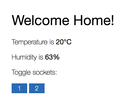
I don't think that code for it is worth posting here, but what's worth is a framework that made it so simple. There are plenty of Rust web frameworks, but I found Rocket to be the most documented and easy-to-use of them all.
Final thoughts
This small project was real fun! I learned a lot about electricity, circuits, MCUs and inter-device communication. I also wrote some more or less real-world Rust, and was really surprised how simple it was to program in it and how well it worked on RPi.